Consider the Valve opening Mechanism Shown in Fig 2 Again
Introduction to Mechanisms
with
Susan Finger
Stephannie Behrens
Table of Contents
5 Planar Linkages
v.ane Introduction
five.1.1 What are Linkage Mechanisms?
Have you ever wondered what kind of mechanism causes the current of air shield wiper on the forepart widow of machine to oscillate ( Effigy 5-1a)? The mechanism, shown in Effigy 5-1b, transforms the rotary motion of the motor into an oscillating motion of the windshield wiper.
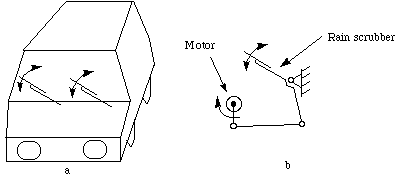
Effigy 5-i Windshield wiper
Let'southward make a simple machinery with similar beliefs. Take some cardboard and brand four strips equally shown in Figure 5-2a.
Take four pins and get together them as shown in Figure five-2b.
Now, hold the 6in. strip so information technology can't move and turn the 3in. strip. You lot volition see that the 4in. strip oscillates.
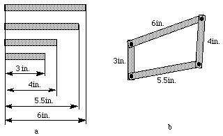
Effigy 5-2 Practise-it-yourself 4 bar linkage mechanism
The four bar linkage is the simplest and often times, the most useful mechanism. Every bit we mentioned before, a mechanism equanimous of rigid bodies and lower pairs is called a linkage (Hunt 78). In planar mechanisms, there are just ii kinds of lower pairs --- revolute pairs and prismatic pairs.
The simplest closed-loop linkage is the four bar linkage which has four members, three moving links, one fixed link and 4 pin joints. A linkage that has at least one stock-still link is a mechanism. The post-obit example of a four bar linkage was created in SimDesign in simdesign/fourbar.sim
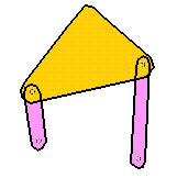
Figure 5-three Iv bar linkage in SimDesign
This machinery has iii moving links. Two of the links are pinned to the frame which is not shown in this moving picture. In SimDesign, links can be nailed to the background thereby making them into the frame.
How many DOF does this mechanism have? If we want it to take only one, we can impose one constraint on the linkage and it will take a definite motion. The iv bar linkage is the simplest and the most useful mechanism.
Reminder: A machinery is composed of rigid bodies and lower pairs called linkages (Hunt 78). In planar mechanisms there are just two kinds of lower pairs: turning pairs and prismatic pairs.
5.i.2 Functions of Linkages
The function of a link mechanism is to produce rotating, oscillating, or reciprocating motion from the rotation of a crank or vice versa (Ham et al. 58). Stated more than specifically linkages may be used to convert:
- Continuous rotation into continuous rotation, with a constant or variable angular velocity ratio.
- Continuous rotation into oscillation or reciprocation (or the reverse), with a constant or variable velocity ratio.
- Oscillation into oscillation, or reciprocation into reciprocation, with a constant or variable velocity ratio.
Linkages accept many dissimilar functions, which can exist classified according on the main goal of the mechanism:
- Function generation: the relative motion between the links continued to the frame,
- Path generation: the path of a tracer point, or
- Motion generation: the motion of the coupler link.
5.2 Four Link Mechanisms
1 of the simplest examples of a constrained linkage is the four-link mechanism . A variety of useful mechanisms tin be formed from a four-link mechanism through slight variations, such as changing the grapheme of the pairs, proportions of links, etc. Furthermore, many complex link mechanisms are combinations of 2 or more such mechanisms. The majority of 4-link mechanisms fall into 1 of the following two classes:
- the four-bar linkage machinery, and
- the slider-crank mechanism.
5.2.ane Examples
Parallelogram Machinery
In a parallelogram four-bar linkage, the orientation of the coupler does non change during the motion. The figure illustrates a loader. Obvioulsy the beliefs of maintaining parallelism is important in a loader. The bucket should not rotate as information technology is raised and lowered. The corresponding SimDesign file is simdesign/loader.sim.

Effigy 5-iv Front loader mechanism
Slider-Crank Mechanism
The iv-bar mechanism has some special configurations created by making one or more links space in length. The slider-creepo (or crank and slider) machinery shown below is a four-bar linkage with the slider replacing an infinitely long output link. The corresponding SimDesign file is simdesign/slider.crank.sim.
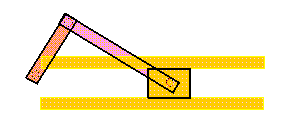
Figure 5-5 Creepo and Slider Mechanism
This configuration translates a rotational motion into a translational ane. Virtually mechanisms are driven past motors, and slider-cranks are oft used to transform rotary motion into linear motion.
Crank and Piston
Yous can also use the slider equally the input link and the creepo as the output link. In this case, the machinery transfers translational motion into rotary move. The pistons and crank in an internal combustion engine are an example of this type of machinery. The respective SimDesign file is simdesign/combustion.sim.
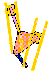
Figure 5-6 Crank and Piston
You might wonder why there is another slider and a link on the left. This machinery has ii expressionless points. The slider and link on the left assist the mechanism to overcome these dead points.
Block Feeder
I interesting awarding of slider-crank is the block feeder. The SimDesign file can exist found in simdesign/block-feeder.sim
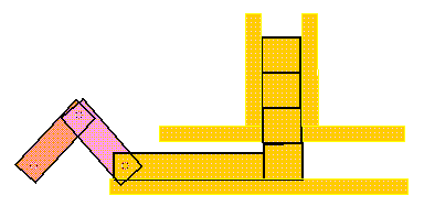
Figure 5-7 Block Feeder
5.2.two Definitions
In the range of planar mechanisms, the simplest group of lower pair mechanisms are 4 bar linkages. A four bar linkage comprises four bar-shaped links and four turning pairs as shown in Figure v-8.

Figure 5-eight Iv bar linkage
The link contrary the frame is called the coupler link, and the links whick are hinged to the frame are called side links. A link which is gratuitous to rotate through 360 degree with respect to a 2nd link will be said to revolve relative to the 2nd link (not necessarily a frame). If it is possible for all iv bars to become simultaneously aligned, such a country is called a change point.
Some important concepts in link mechanisms are:
- Creepo: A side link which revolves relative to the frame is called a crank.
- Rocker: Any link which does not revolve is chosen a rocker.
- Crank-rocker mechanism: In a four bar linkage, if the shorter side link revolves and the other one rocks (i.e., oscillates), it is chosen a creepo-rocker mechanism.
- Double-crank mechanism: In a four bar linkage, if both of the side links circumduct, it is called a double-crank machinery.
- Double-rocker mechanism: In a four bar linkage, if both of the side links rock, it is called a double-rocker mechanism.
5.2.three Classification
Before classifying four-bar linkages, we demand to introduce some basic nomenclature.
In a 4-bar linkage, we refer to the line segment betwixt hinges on a given link as a bar where:
- s = length of shortest bar
- fifty = length of longest bar
- p, q = lengths of intermediate bar
Grashof's theorem states that a four-bar mechanism has at least i revolving link if
(5-ane)
and all three mobile links will rock if
(five-2)
The inequality 5-ane is Grashof'south criterion.
All four-bar mechanisms autumn into 1 of the four categories listed in Tabular array 5-1:
| Case | l + s vers. p + q | Shortest Bar | Type |
|---|---|---|---|
| ane | < | Frame | Double-crank |
| 2 | < | Side | Rocker-crank |
| 3 | < | Coupler | Doubl rocker |
| 4 | = | Any | Change point |
| v | > | Whatever | Double-rocker |
From Table 5-ane nosotros can run into that for a mechanism to have a crank, the sum of the length of its shortest and longest links must be less than or equal to the sum of the length of the other two links. However, this condition is necessary but not sufficient. Mechanisms satisfying this condition fall into the following three categories:
- When the shortest link is a side link, the mechanism is a crank-rocker machinery. The shortest link is the creepo in the mechanism.
- When the shortest link is the frame of the mechanism, the machinery is a double-crank machinery.
- When the shortest link is the coupler link, the mechanism is a double-rocker machinery.
5.2.four Transmission Bending
In Effigy five-eleven, if AB is the input link, the force practical to the output link, CD, is transmitted through the coupler link BC. (That is, pushing on the link CD imposes a force on the link AB, which is transmitted through the link BC.) For sufficiently slow motions (negligible inertia forces), the forcefulness in the coupler link is pure tension or compression (negligible angle activity) and is directed along BC. For a given strength in the coupler link, the torque transmitted to the output bar (about indicate D) is maximum when the angle  between coupler bar BC and output bar CD is
  /2. Therefore, angle BCD is chosen transmission angle.

(5-3)
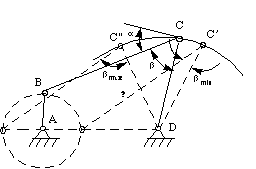
Figure v-eleven Manual angle
When the manual angle deviates significantly from  /two, the torque on the output bar decreases and may not be sufficient to overcome the friction in the system. For this reason, the deviation angle
  =|
=| /two-
/two- | should not be too dandy. In practice, there is no definite upper limit for
  , because the existence of the inertia forces may eliminate the undesirable force relationships that is present nether static atmospheric condition. Nevertheless, the following criterion can be followed.
five.2.five Dead Point
When a side link such as AB in Figure v-10, becomes aligned with the coupler link BC, it can but be compressed or extended by the coupler. In this configuration, a torque applied to the link on the other side, CD, cannot induce rotation in link AB. This link is therefore said to exist at a dead signal (sometimes called a toggle point).
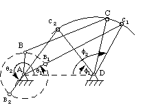
Figure 5-ten Dead point
In Figure 5-11, if AB is a crank, information technology can go aligned with BC in full extension forth the line AB1C1 or in flexion with AB2 folded over B2C2 . We announce the angle ADC by  and the angle DAB past
  . We use the subscript one to denote the extended state and 2 to denote the flexed state of links AB and BC. In the extended land, link CD cannot rotate clockwise without stretching or compressing the theoretically rigid line Air conditioning1 . Therefore, link CD cannot move into the forbidden zone below ConeD, and
  must exist at i of its two farthermost positions; in other words, link CD is at an extremum. A second extremum of link CD occurs with
  =
=  one.
one.
Note that the extreme positions of a side link occur simultaneously with the dead points of the opposite link.
In some cases, the expressionless point tin be useful for tasks such every bit work fixturing (Figure five-xi).
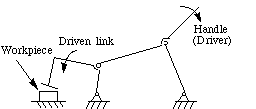
Effigy 5-11 Piece of work fixturing
In other cases, dead indicate should be and tin can be overcome with the moment of inertia of links or with the asymmetrical deployment of the machinery (Figure five-12).
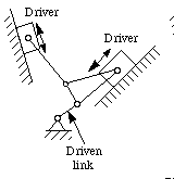
Figure 5-12 Overcoming the dead bespeak past asymmetrical deployment (5 engine)
5.2.6 Slider-Crank Mechanism
The slider-crank mechanism, which has a well-known awarding in engines, is a special case of the crank-rocker mechanism. Notice that if rocker 3 in Figure 5-13a is very long, it can be replaced by a block sliding in a curved slot or guide as shown. If the length of the rocker is space, the guide and block are no longer curved. Rather, they are apparently straight, equally shown in Figure v-13b, and the linkage takes the grade of the ordinary slider-crank mechanism.
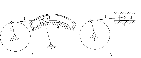
Figure 5-13 Slider-Crank mechanism
5.2.vii Inversion of the Slider-Crank Mechanism
Inversion is a term used in kinematics for a reversal or interchange of form or part equally practical to kinematic bondage and mechanisms. For example, taking a different link every bit the fixed link, the slider-crank mechanism shown in Figure v-14a can be inverted into the mechanisms shown in Effigy v-14b, c, and d. Different examples tin can be establish in the awarding of these mechanisms. For example, the mechanism of the pump device in Figure 5-xv is the same as that in Effigy 5-14b.
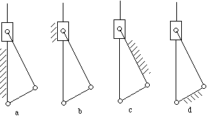
Effigy 5-14 Inversions of the creepo-slide mechanism
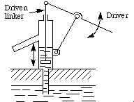
Figure 5-fifteen A pump device
Proceed in mind that the inversion of a machinery does not modify the motions of its links relative to each other just does change their accented motions.
![]()
Table of Contents
- Complete Table of Contents
- 1 Concrete Principles
- 2 Mechanisms and Simple Machines
- three More than on Machines and Mechanisms
- four Basic Kinematics of Constrained Rigid Bodies
- v Planar Linkages
- 5.1 Introduction
- v.ane.ane What are Linkage Mechanisms?
- 5.one.2 Functions of Linkages
- five.2 Four Link Mechanisms
- v.2.1 Examples
- 5.2.two Definitions
- 5.2.3 Classification
- 5.two.4 Transmission Angle
- 5.two.v Dead Point
- 5.2.6 Slider-Creepo Machinery
- 5.2.7 Inversion of the Slider-Crank Mechanism
- 5.1 Introduction
- half dozen Cams
- 7 Gears
- 8 Other Mechanisms
- Alphabetize
- References
![]()


sfinger@ri.cmu.edu
Source: https://cs.cmu.edu/~rapidproto/mechanisms/chpt5.html
0 Response to "Consider the Valve opening Mechanism Shown in Fig 2 Again"
Enregistrer un commentaire